WaveTrace Proof of Concept: It Works!
I had a reading break from uni, so I decided to put together a proof of concept to see if I could make a rudimentary version of WaveTrace - and it worked!
The Mount
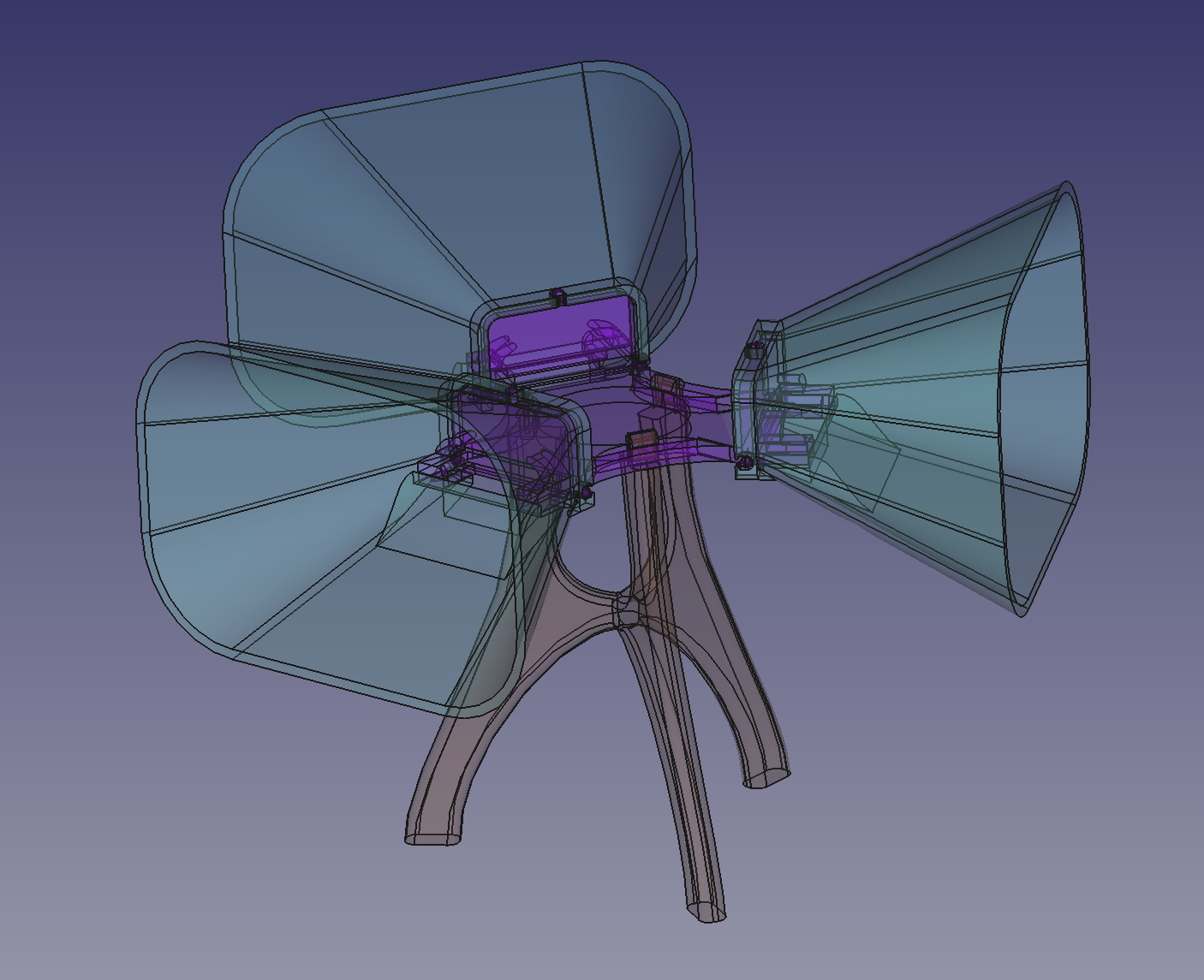
I had already bought some omnidirectional USB microphones a while back for this project, so I adapted them with 3D printed cones to directionally bias them. I also 3D printed a mount that holds the microphones and the cones above the ground:
Connecting the Microphones
I connected the microphones to my laptop with a 3 way usb splitter. However, when I tried to read audio from them with PortAudio, I got an error about improper channel count. Apparently this is due to the fact that PortAudio expects at least one output channel, which to me seems silly; if you just have a microphone there shouldn’t be output.
From the PortAudio documentation:
The number of channels of sound to be delivered to the stream callback or accessed by Pa_ReadStream() or Pa_WriteStream(). It can range from 1 to the value of maxInputChannels in the PaDeviceInfo record for the device specified by the device parameter.
While it references maxInputChannels instead of maxOutputChannels, the fact remains that it was throwing a channel count error when I was trying to open one of the usb mics, which had 1 input channel and 0 output channels.
In any case, I worked around this by creating a virtual device using the PulseAudio sound server (which was already running as part of my desktop environment). The bash script I wrote for this is similar to the one I made for mono audio output:
pactl load-module module-null-sink channels=3 channel_map=left,center,right rate=44100 sink_name=wavetrace sink_properties="device.description='WaveTrace'"
pactl load-module module-loopback source=alsa_input.usb-C-Media_Electronics_Inc._USB_PnP_Sound_Device-00.2.analog-mono sink=wavetrace channel_map=left
pactl load-module module-loopback source=alsa_input.usb-C-Media_Electronics_Inc._USB_PnP_Sound_Device-00.3.analog-mono sink=wavetrace channel_map=center
pactl load-module module-loopback source=alsa_input.usb-C-Media_Electronics_Inc._USB_PnP_Sound_Device-00.analog-mono sink=wavetrace channel_map=right
The script creates a virtual null sink (essentially a dummy virtual audio device with three channels and no default inputs or outputs), and then maps one microphone (the ID of which starts with “usb-C-Media…”) to each channel. This device is also created with three output channels, which makes PortAudio happy (no more errors!).
Another benefit of this is that I only have to open one PortAudio stream which can handle microphone input by channel. This way, audio data between mics is already synced up (as opposed to having a separate stream and callback for each mic).
Processing the Audio
To process the audio, I put together the tests and proof of concepts that I built previously with FFTW and PortAudio (PA). The PA callbacks write the sound data from each microphone to a separate AudioBuffer object, and FFTProcessor objects read data from these buffers and compute FFTs each time there is new data. Since this is a proof of concept, I have temporarily hard-coded an array size of \(8192\) (which is \(4\times1024\)) for the array of audio to be processed.
Then, the WaveTracer object comes into play. This object is in charge of figuring out where sounds are coming from based on the FFTs. The object iterates through the output frequency components, and for each such component creates three vectors, one for each microphone. The vectors have a magnitude which is proportional to the magnitude of the frequency component being analyzed at that microphone, and the vector’s direction reflects the physical position of the respective microphone:
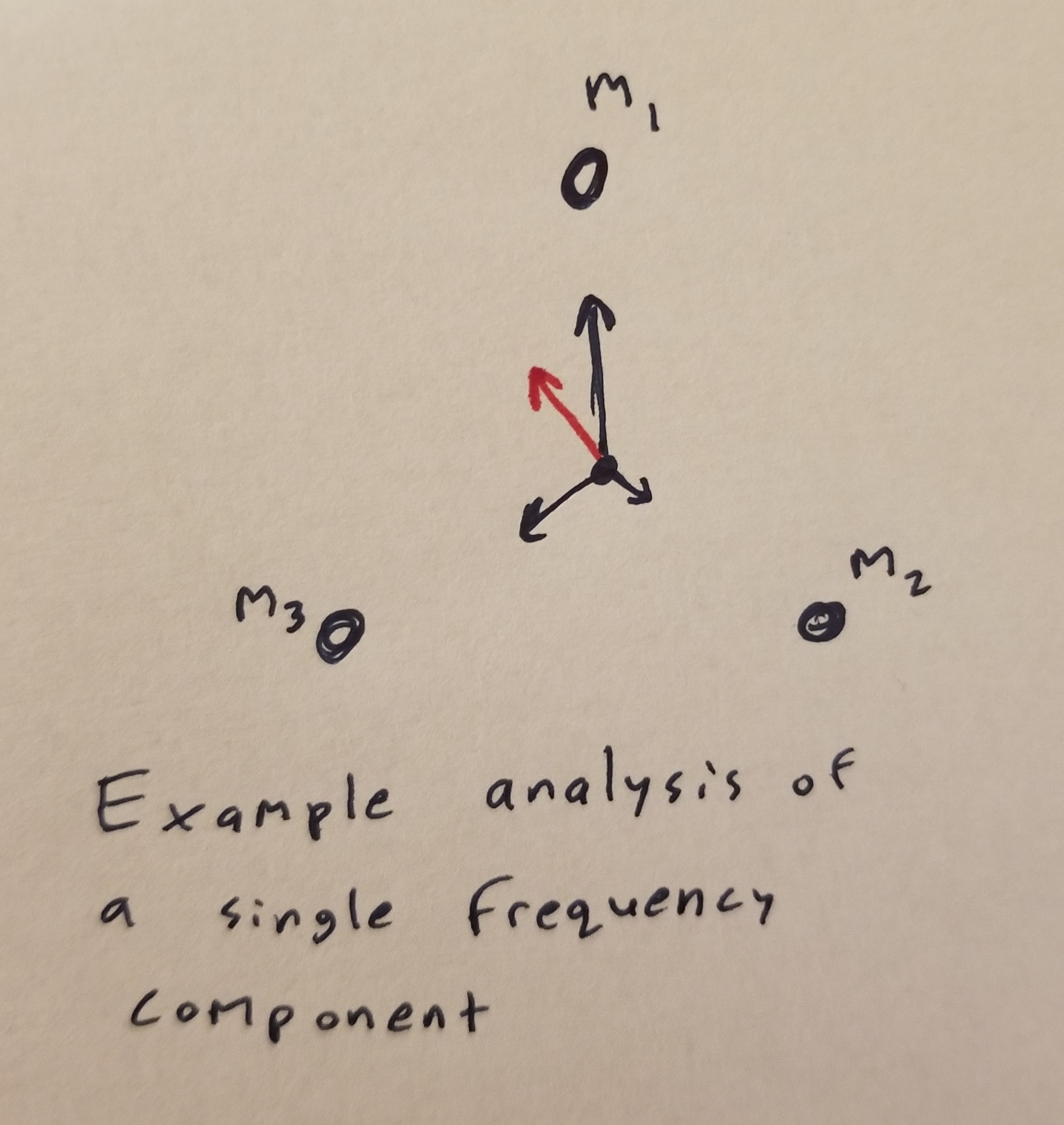
Consider the above image. The frequency component has highest intensity at mic 1 (\(m_1\)), medium intensity at mic 3 (\(m_3\)), and lowest intensity at mic 3 (\(m_3\)); the microphones are illustrated as dots. The black vectors are the vectors that WaveTracer creates to represent the frequency components as detected by each microphone. These vectors are added to get the red vector, which represents the overall direction and magnitude of the frequency component being analyzed. Note that if all the magnitudes of the black vectors are the same, the red vector will have magnitude 0; essentially, the red vector’s represents not quite the magnitude of this frequency, but the directional magnitude (how much it is biased in a certain direction).
Every time we want to calculate new data, the WaveTracer iterates through all the frequency components that are outputted by the FFTs, and stores the output vectors in an array to be later read and visualized.
Visualizing the Output
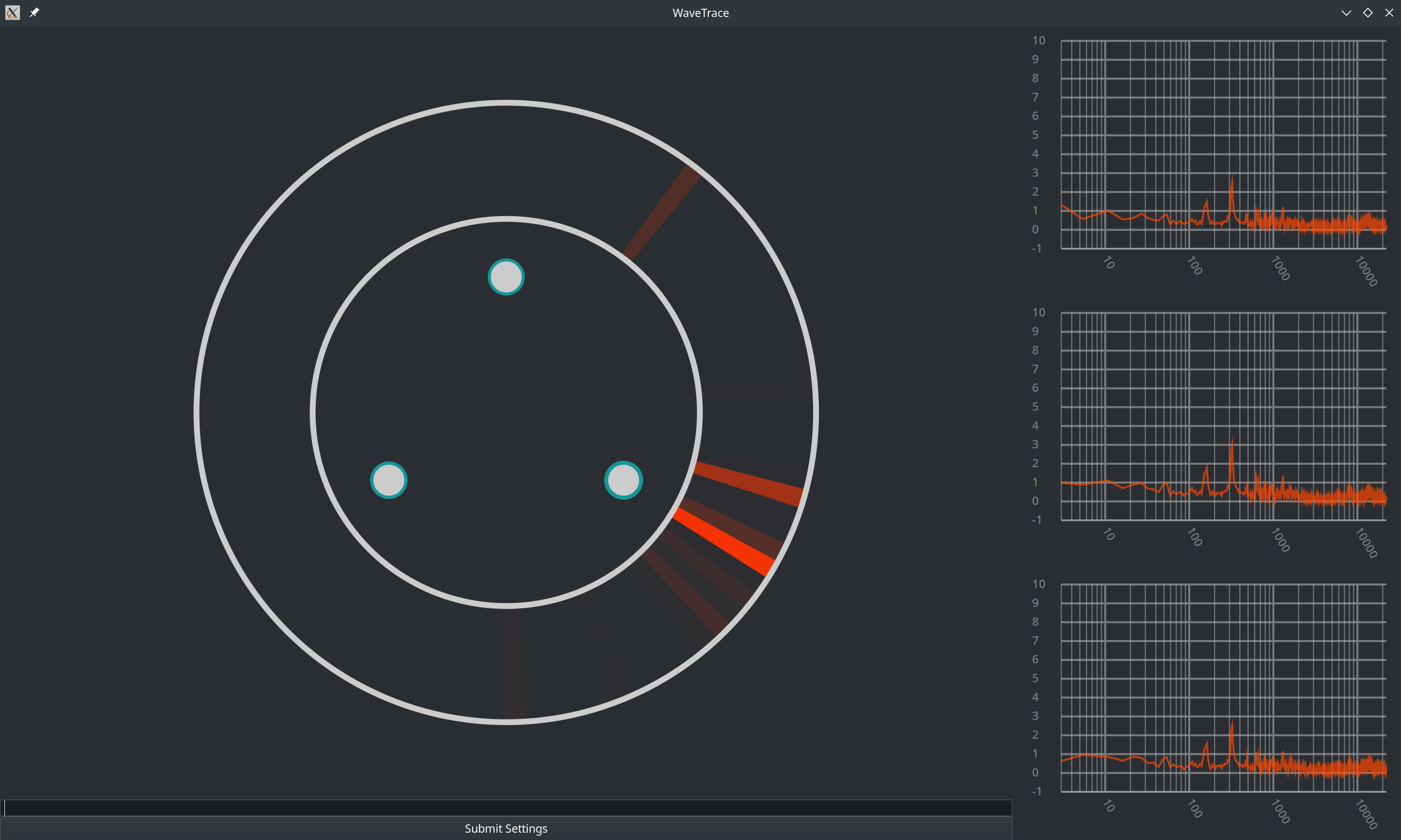
The output of the WaveTracer is visualized in another custom Gtk widget that I created, which I dubbed the AudioCompass. This audio compass first reads the output of the WaveTracer, sorting it into chunks. The sum of magnitudes of the vectors in a given chunk determines the brightness of that chunk; if many frequencies originate from a similar direction and have large magnitudes, the respective chunk will be brighter:
It Works!! :D
See below a video of a screen recording of WaveTrace picking up two sine waves (with distinct frequencies) emitted by two separate cell phones as I move them around:
While the signal is somewhat shaky at times, it is mostly accurate (I will upload a video which also shows me moving the phones soon).
Overall, I’m glad that I got a proof of concept working, and I’m looking forward to continuing this project by refining what I’ve built so far, and then building the next layer ontop of it. I’m hoping that with proper directional mics and some more refined processing, I’ll be able to more reliably pick out sounds, and this improved version will act as a foundation for the next steps in this project.
For now, I’ve got to study for exams, so see ya later!