Robot Summer
This summer I did what they call “Robot Summer” at UBC Engineering Physics. In the May through June summer semester I took 4 full classes plus a robot class (ENPH 253) which lasted from May through August.
The robot class was by far the highlight! In teams of four, we had to build fully autonomous robots to accomplish tasks and compete against the other teams (read more here, and check out this video; My robot is the one with the purple basket!). This year, the scenario was that there was a animal hospital on fire, and we needed to save as many “pets” (stuffed animals) as we could within 2 minutes.
The awesome thing about this class is that we were given minimal direction in terms of how to build our robots; they basically gave us the rules for the competition and let us run amok in the lab. We spent May through June mostly working on our other classes, though we definitely spent time coming up with ideas and designs for the robots. Starting in July, the robot lab was open 5 days a week from 10am to 8pm (10 hours a day!!), and I spent just about every hour I could in the lab!
There was so much to do, including mechanical prototyping (CAD, 3D printing, machining metal parts with the lathe and mill, etc), electrical design (PCBs for motor drivers and breakout boards, figuring out power budgets, isolation between the microcontroller and the power circuits, etc), and software design (writing firmware for the robot, abstracting away the hardware, etc).
I was mainly involved in the electrical and software design, though I also contributed somewhat to the mechanical design; in general, me and my teammates would run ideas past each other quite often, and as a result we all contributed in some fashion to many aspects of the robot!
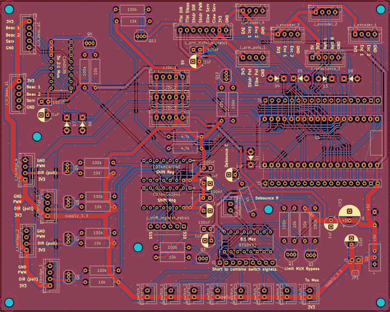
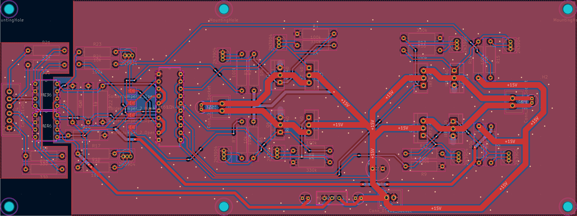
I designed two PCBs (and made numerous one-off proto boards); I designed an H-Bridge board and a breakout board for our ESP32 microcontroller (see below images). The KiCAD files are available here.
Breakout Board PCB in KiCAD:
H-Bridge PCB in KiCAD:
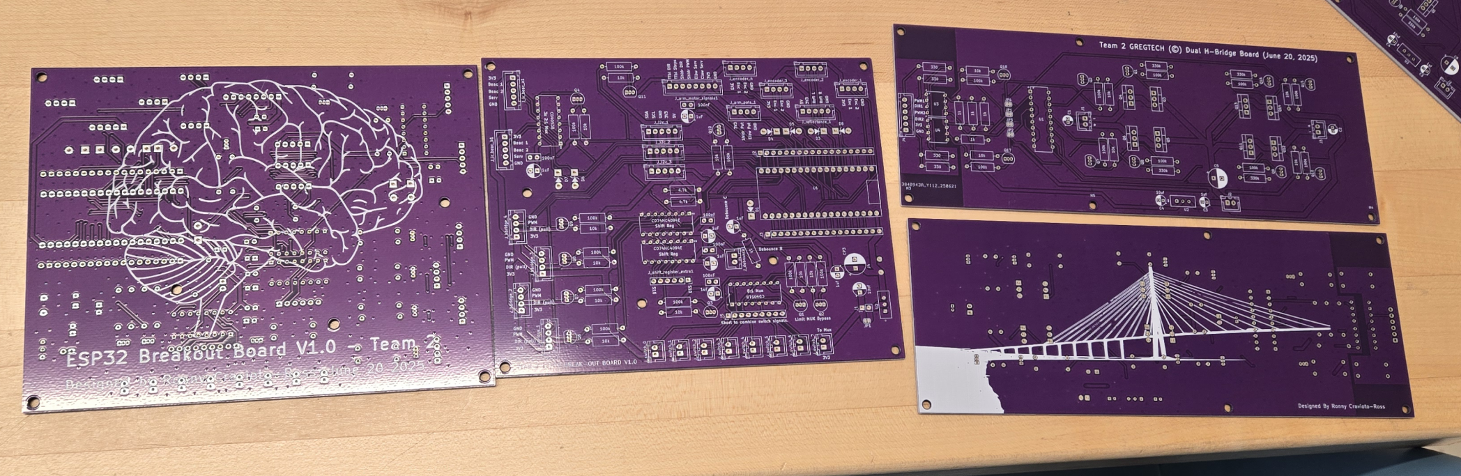
Both PCBs After Arriving from JLCPCB:
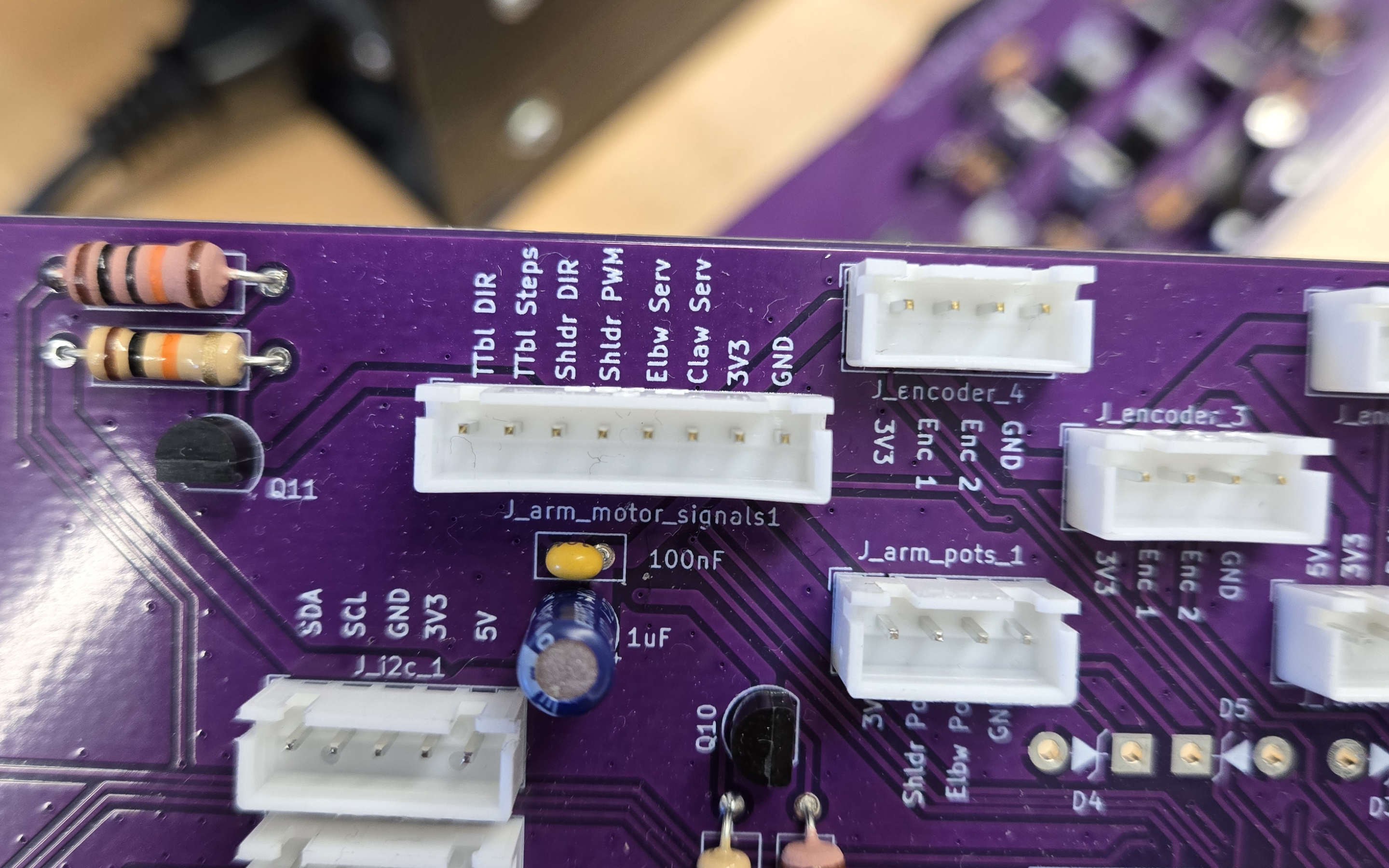
Part of the Populated Breakout Board:
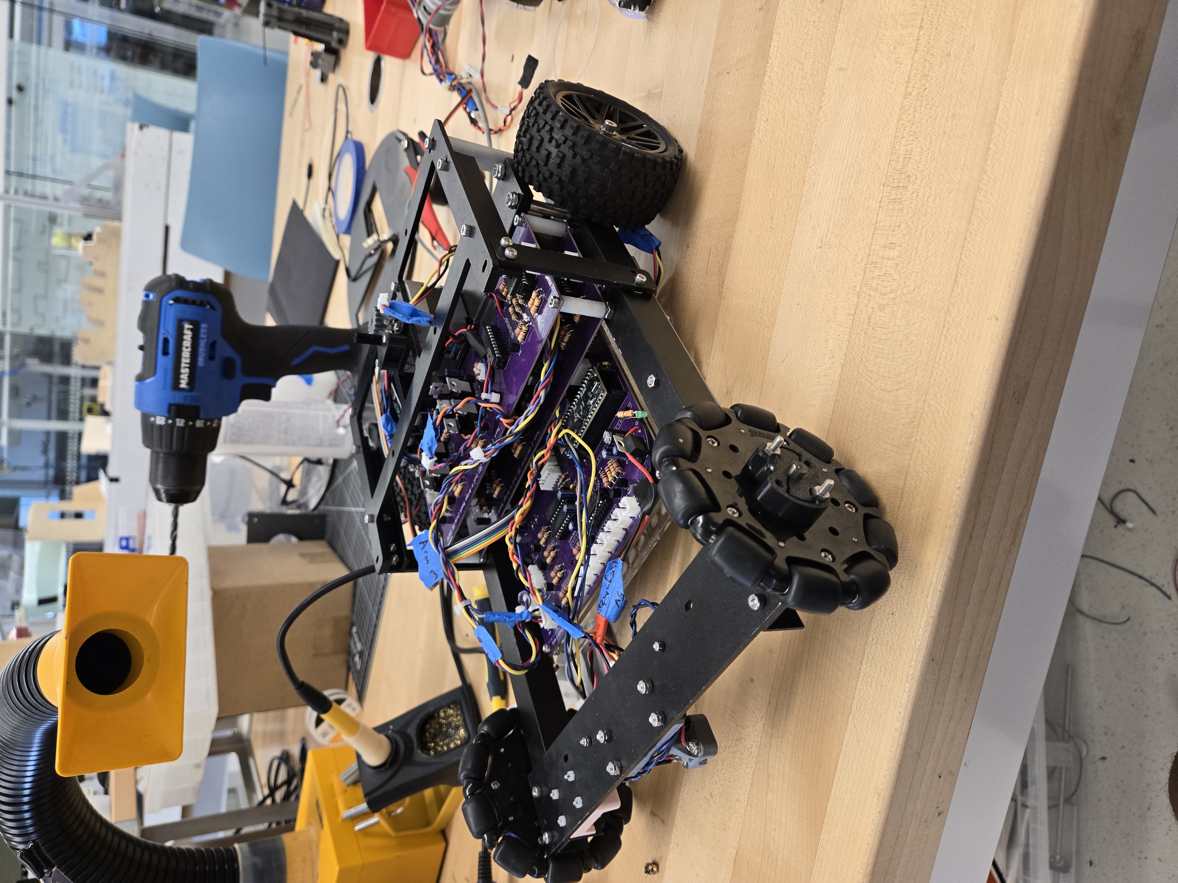
Robot Partially Assembled:
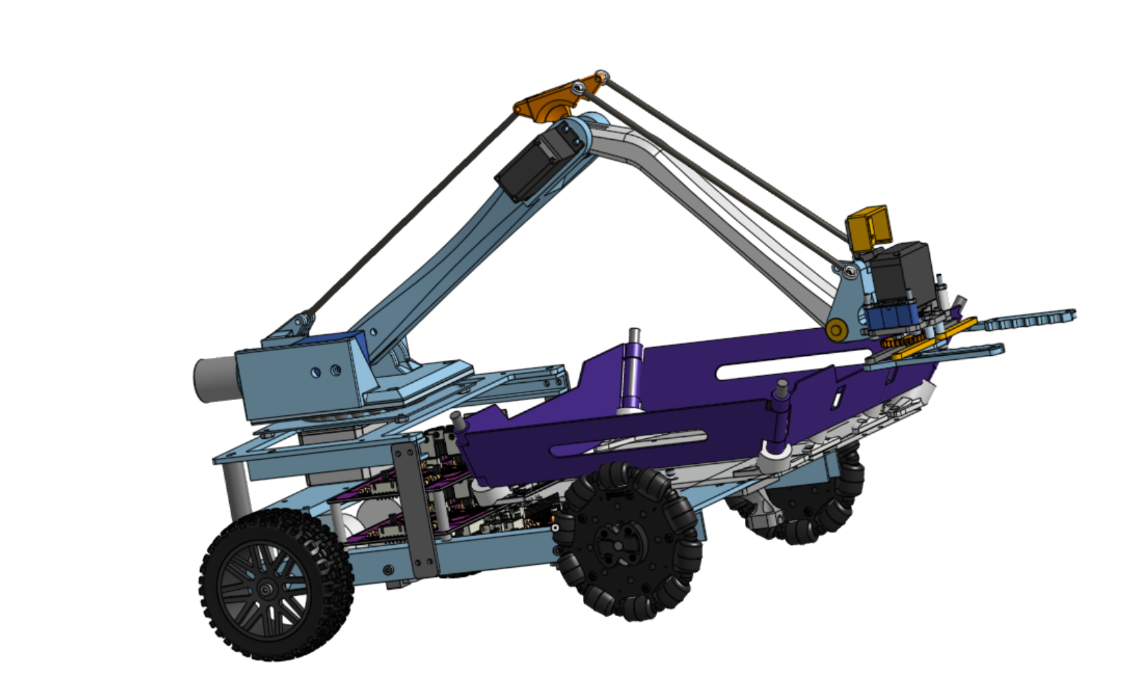
Full Robot CAD:
Debugging UI Screenshots:
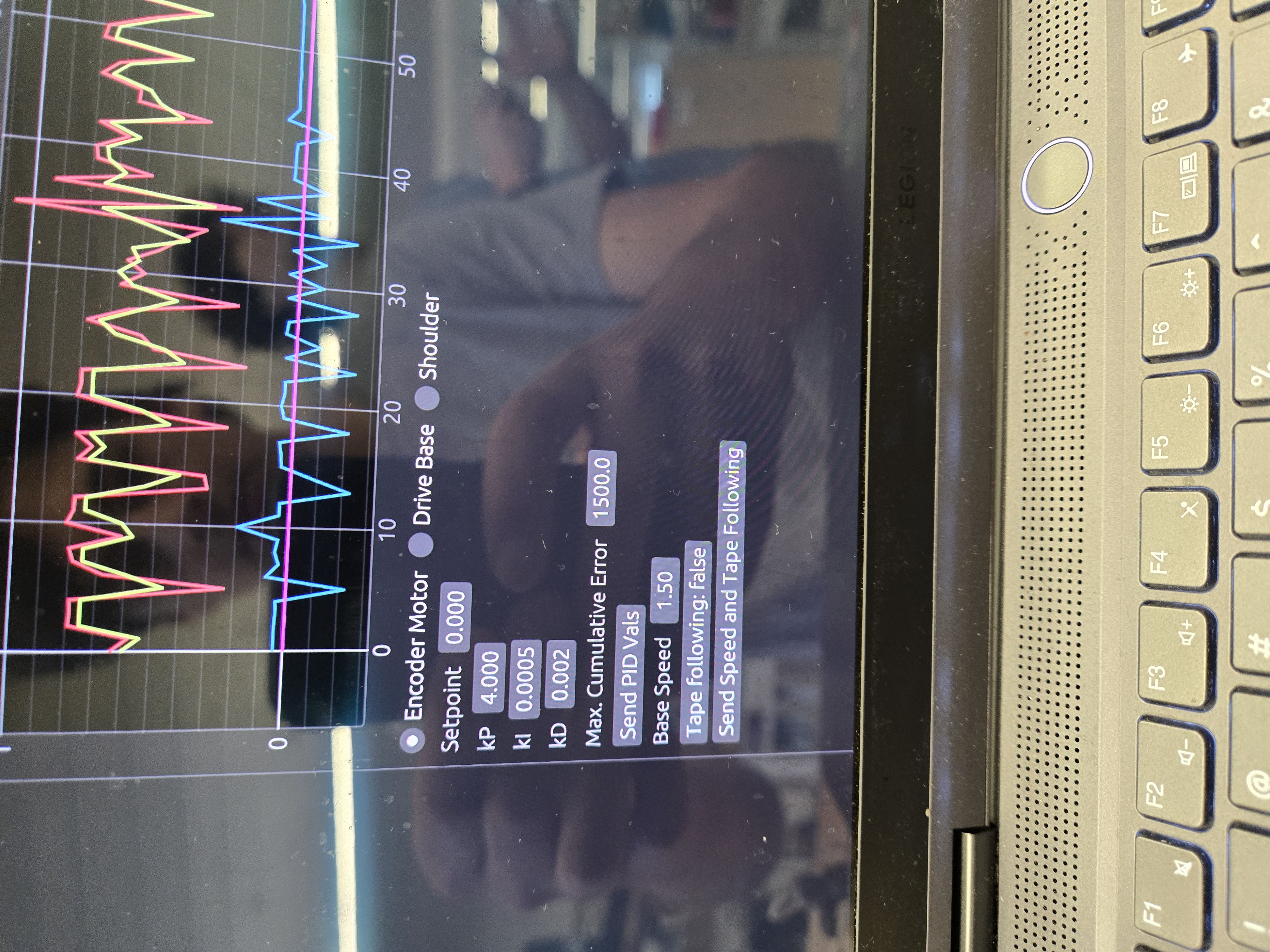
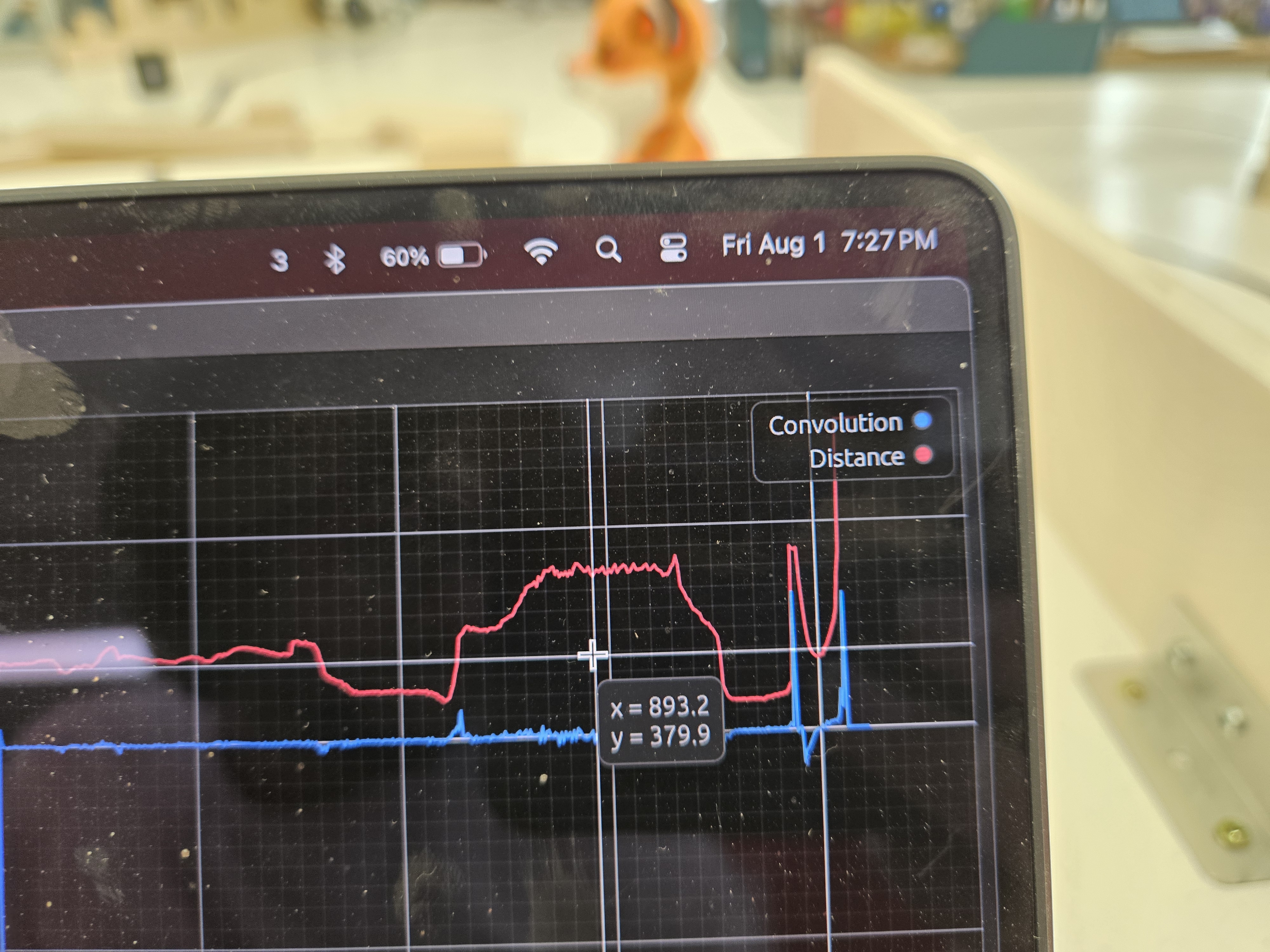
Top image is for PID debugging/tuning, bottom image is ToF sensor output (as well as convolution filter output). Not shown is the odometry location tracking visualization.
Robot Competition Video:
See my team getting interviewed and our robot in action at 0:55!!
Software
A quick disclaimer: All this code was written under intense time pressure, sleep deprivation, etc., (:P) so be aware that it does not necessarily reflect my best work (especially in terms of documentation and whatnot).
For the software, we wrote over 4,000 lines of firmware to control all the motors, read all the sensors, and control the robot (e.g. moving the arm to certain positions, follow a black line of tape on the field, etc). We used PID controllers all over the place, for example our wheels were velocity PID controlled using magnetic encoders, one of our arm joints was a DC motor with a potentiometer attached which would use PID control to go to whichever angle, and the tape following algorithm changed the rate of turning using a PID controller too.
There were some non-trivial bits of code in there, such as inverse kinematics using cubic-spline approximated inverse trig functions (for computational speed at the cost of accuracy), quadrature encoder reading using interrupts, interrupt/timer-based pulse generation for stepper motor control, I2C sensor integration, ring-buffer and interrupt based UART output to avoid performance hit when debugging, odometry position tracking, among many other things!
The codebase is available at github.com/enphx/firmware. Note that due to debugging some crazy bugs last minute (which turned out to be hardware bugs instead of software bugs lol) there are a lot of strange commits, such as us switching between doubles and floats in the hopes of the bug magically going away… (we were desperate hehe).
On top of all this, I also wrote a serial interface which allowed us to talk to the robot in real time! This allowed us to:
- Troubleshoot PID issues by viewing the PID’s inputs, set point, and outputs.
- Adjust the arm’s position in real time.
- Look at the robot’s odometry output (where the robot thinks it is based on how far the wheels have moved).
- View the live lidar distance value, which was useful for deciding on distance thresholds for pet detection.
The code for the serial interface can be found on my github.
We spent a lot of time and effort on our robot, and it paid off, since we got first place at the competiton!!